Heavy-Duty Connector
The connector body gives the internal assembly a durable external structure.


INSIDE THE CONNECTION.
A closer look at the solid-core connector construction described in the engineering catalog.
A CLOSER LOOK / SOLID-CORE CONSTRUCTION
Swipe across the diagram to read each annotation. The numbered details continue below.

The value is in how the materials work together: stable contacts, insulated conductors, a rigid frame and a comfortable outer grip.
The connector body gives the internal assembly a durable external structure.
The specified CuBe spring material supports repeated mechanical contact; the catalog pairs it with 5 μm silver plating.
A sealing element helps protect the relevant mating area as part of the overall connector construction.
Securely crimped to copper conductor, creating a low-resistance connection and minimal heat during high-current charging. No soldered joint is used.
Individual conductor insulation separates the current-carrying paths.
The overmolding securely encases and locks the cable jacket in place. The reinforced joint withstands a sustained 50 kg pull, providing exceptional mechanical strength.
Injected thermoplastic elastomer fills the internal construction rather than leaving a hollow shell around the assembly.
An internal frame supports alignment and mechanical integrity.
Overmolded grip surfaces make the connector comfortable to handle while adding external protection.
The specified flexible TPU cable completes the connector assembly. Its conductor size, current and phase rating must match the charging setup.
HOLLOW CORE / SOLID CORE
| Construction Detail | Typical Market Hollow-Core Connector | AmpByte Solid-Core Design |
|---|---|---|
| Internal Structure | An empty cavity surrounds the internal assembly. | Injected TPE fills the internal assembly, reducing voids. |
| Sealing Approach | Thin silicone O-rings seal the hollow plastic shell; seal damage can allow water ingress. | Solid-core overmolding surrounds the internal assembly. |
| Assembly | A multi-screw shell assembly can be vulnerable to seal failure under rough handling. | A rigid internal skeleton is enclosed by solid TPE and an overmolded grip. |
| Cable Retention | The cable is secured by a separate end cover and a metal cable clamp. | Overmolding encases and locks the cable jacket in place; the reinforced joint withstands a sustained 50 kg pull. |
| Waterproof | Water entering through a damaged seal can become trapped in the hollow cavity. | Solid-core TPE filling reduces cavities where water and moisture can collect. |
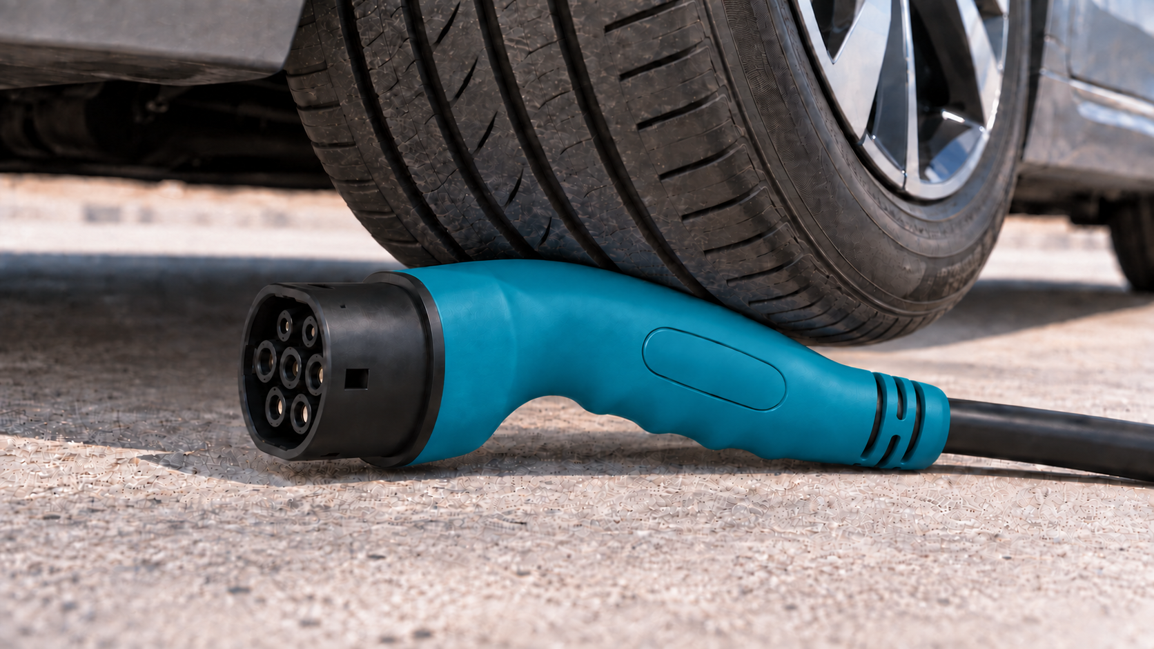
| Mechanical Strength | The hollow shell can crack under impact or crushing, compromising its structure and waterproofing. | The robust solid-core construction withstands repeated vehicle-wheel rollovers while maintaining structural integrity and waterproofing for reliable protection. |
| Electrical Risk | Trapped water can increase the risk of electrical leakage, short circuits and fire. | Solid-core insulation and filling help avoid internal moisture accumulation. |
Comparison of the two constructions and hollow-core limitations described in the engineering catalog, page 4 ↗.